Bird's Eye View Segmentation
In recent years, deep learning methods have advanced at an incredible pace and in this paper we will dive into some of the state of the art segmentation approaches utilized within vehicles and robotic navigation systems. We will study and discuss three different approaches to Bird’s Eye View segmentation: the Lift, Splat, and Shoot method, PointBeV method, and BeVSegFormer method. We also go through our own replication of Lift, Splat, and Shoot and show the capabilities of this deep learning method.
Motivation
Birds Eye View (BeV) Segmentation is crucial for the further development of self-driving cars and autonomous vehicles. Due to the nature of the self-driving cars, we need fast and reliable predictions that can utilize multiple car sensors and cameras. Additionally, cars need a full 360 understanding of their surroundings, but most sensors are directional. BeV segmentation solutions provide this by using sensor fusion (whether through DL or traditional computer vision) to make predictions in the BeV plane, representing the area surrounding the car.
We’ll start with Lift, Splat, Shoot model, which uses CNNs U-Nets, and camera matrices to project camera data into 3d space, then onto the BeV plane [1]. Additionally, we will also analyze the BevSegFormer and PointBeV architectures (FOOTNOTE HERE), which implement newer techniques such as transformers and sparsity to improve performance and efficiency.
Image Segmentation
In order to understand BeV segmentation, we must first understand image segmentation, which is the process of dividing an image into multiple regions representing distinct objects. The process of segmentation typically takes a grid of pixels as input and generates segmentation masks labeled by class. The go-to architecture for image segmentation has been the CNN with architectures such as residual blocks and encoder-decoder networks. Techniques such as transfer learning and R-CNNs are also commonly used.
BeV Segmentation
Instead of segmenting the image directly, Birds Eye View (BeV) Segmentation outputs on the BeV plane, looking top-down at the cameras. You can think of this as trying to draw a map of surrounding cars, pedestrians, etc, based a Google Street View location. Since cameras do not see depth, this can be quite challenging.
To help better understand the task, The authors of the Lift, Splat Shoot paper introduce 3 major properties that should be preserved by any BeV segmentation algorithm[1]:
- Translation Equivariance: Continuous Transformations generated in the inputs should be preserved in the output. Basically, if the input is shifted, the output should be proportionally shifted. This preserves spatial relationships and ensures our model is generating relevant features.For example, if we pass a car, the pixels shift from left to right and the car should move backwards within the BeV plane relative to us.
- Permutation Invariance: Since the inputs are being combined to form the output, the order of the inputs should not affect the process of generating the outputs and the output itself. Without Permutation Invariance, we cannot expect reliable predictions. For example, if we were to swap the left and right cameras and update their extrinsic matrices, predictions should stay the same.
- Ego-Frame Isometry Equivariance: The position of a camera relative to the car should not affect the location of the generated predictions in 3d space. For example, if the front-left and back-left cameras both see a car, the predictions generated by each camera should be in the same location relative to the car.
Implementation
The first approach to BeV we’ll be exploring is Lift, Splat, and Shoot. Lift extracts features from the image and constructs a 3d feature space to infer depth from image data. Splat flattens the feature space onto the BeV image coordinate system, and segments pixels in BeV space based on the input features. Shoot uses the prediction data to perform motion planning, relevant to autonomous driving. [1]
Lift
First, the Lift step brings the input data into feature space by converting from a 2D local dimension to a 3D frame shared across all cameras. Thus, when extracted into features, it maintains all properties and the features generated aren’t camera specific.
However, when converting to feature space the individual point vectors to each pixel have an ambiguous depth. In order to solve this, the a CNN generates representations within the 3D frame for all possible depths, which consists of a context vector and a depth “attention” vector. At this point, a large point cloud is created from each pixel being projected into 3d space, and the vectors corresponding to each point. The position of each point is depends on the the camera’s intrinsic and extrinsic matrices (position in the world and focal length/field of view, respectively), and the location of the pixel in the image. The shape of these point clouds are frustums - think of the image shooting outwards from the camera in a cone.
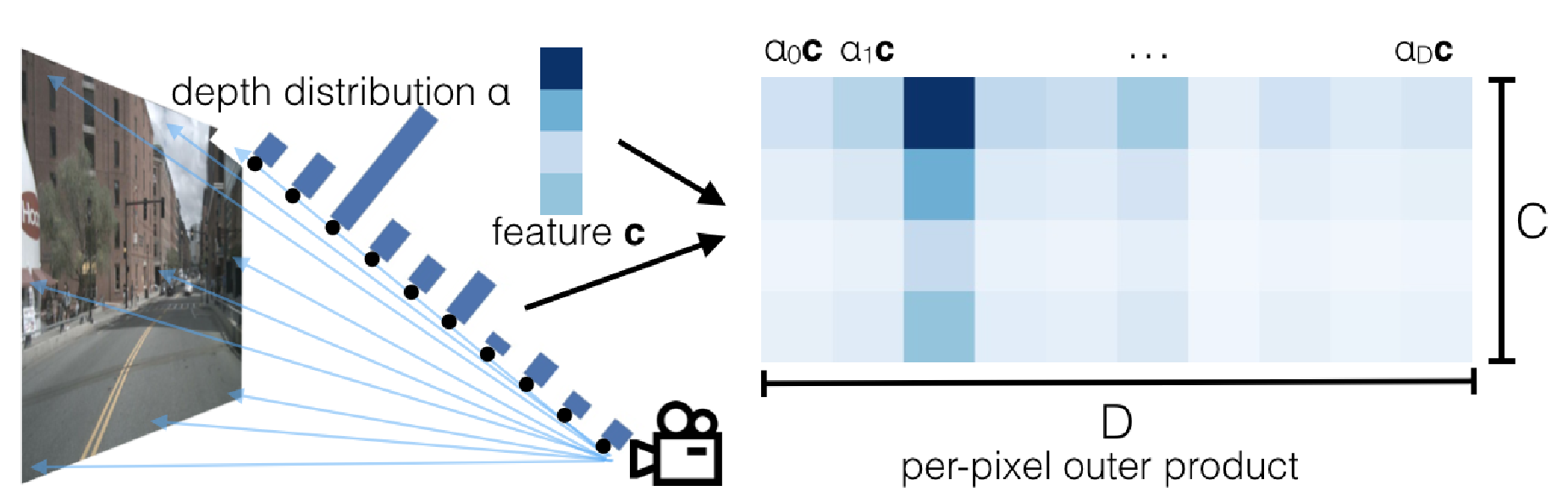
Fig 1. Visualization of the per-pixel predictions generated by the Lift model. The per-pixel context vector scaled with a “attention” vector, which describes the depths the context is most relevant to. [1]
Splat
Splat takes these frustums and joins them in one singular BeV representation. By doing this in feature space, the model can significantly reduce parameters. Since BeV is traditionally used in self-driving cars, by splatting in feature space, we can reduce the amount of memory and time needed to generate predictions. Splat primarily uses a technique called pillar pooling. Traditional pillar pooling consists of aggregating data regions into localized pillars. In this case, we are taking the frustum point clouds and aggregating them into voxels of infinite height. These voxels are then vectorized and processed as tensors by the CNN into a binary segmentation image, representing whether a vehicle is at a location or not.
Shoot
The Shoot phase of the architecture consists of using a Neural Motion Planner and running a cost-map learning on the inputted data. Neural Motion Planners are an architecture designed to predict a distribution over K template trajectories. In this case, a template trajectory is the path the predictor is moving transposed to relative opposite paths for all the objects in the BeV space. The final aspect of Shoot is running the actual segmentation algorithms, for Labels we use the L2 distance from these template trajectories and run the analysis to split the space into regions.
Replication
We were able to replicate the results produced by Philion and Fidler from their provided Github Repository and model weights. On the nuscenes v1.0-mini dataset, the provided model achieved and IoU of 0.357 on a validation set of 81 samples, which is similar to the 33.03 given by the repository description, and the 32.07 IoU described in the paper. Inference on the validation samples took approximately 6.7 seconds on CPU.
Procedure
- Environment Setup - As specified by the instructions provided on the Github repository, we installed
nu-scenes-devkit,tensorboardX, andefficientnet_pytorch. - Dataset - The full nuscenes dataset was too large to download and set up on our local machine, so we downloaded nuscenes-mini, a subset of the data which with fewer scenes.
- Run the model - To run the model, we moved nuscenes to the correct location and downloaded pretrained model weights. Due to the age of the paper, the environment used Python 3.7, and we were unable to perform inference on GPU.
In addition to the IoU benchmarks, authors also provided utilities for visualization, which we tested with success. On visualization, the six camera images is transformed into binary segmentation the BeV plane, with an additionalmap overlay from the nuscenes dataset.
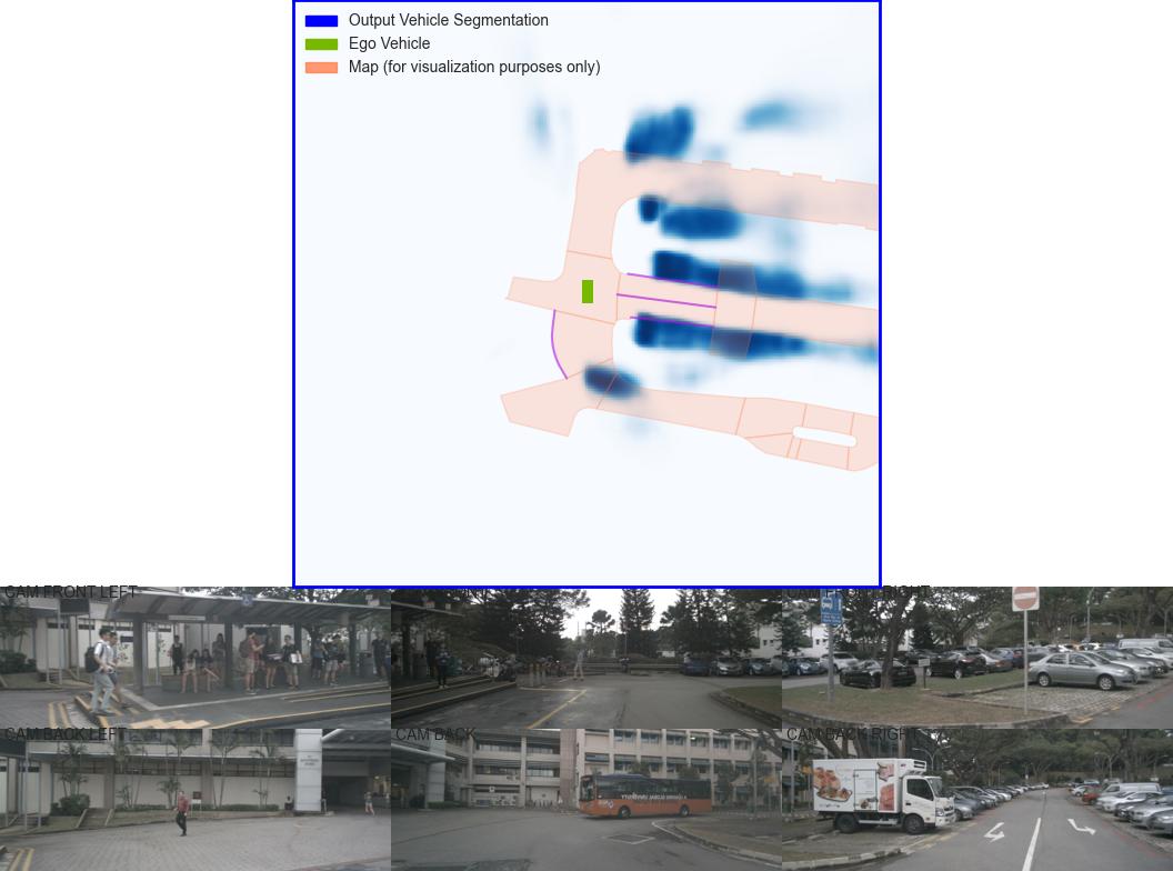
Fig 2. Visualization of Inference on nuscenes-mini
Additional Approaches
PointBEV
Motivation
Traditional BEV approaches rely on fixed-resolution grids, like BeVSegFormer, leading to inefficient resource allocation as they uniformly allocate computational effort across all areas of the grid. These methods often face significant memory and computational challenges, especially when attempting to aggregate information from long temporal contexts.
PointBEV introduces sparse BEV representations to focus computational resources on specific areas of interest, improving efficiency. This approach is particularly well-suited for memory-constrained platforms. By using a sparse representation of data, PointBEV can dynamically allocate resources and improve robustness to projection errors, making it well-suited for long-term temporal analysis.
Architecture
PointBeV combines three key components: Sparse Feature Pulling, a two-stage course/fine learning strategy that allows the model to train with fewer points, and a submanifold temporal attention to create an efficient and scalable architecture.
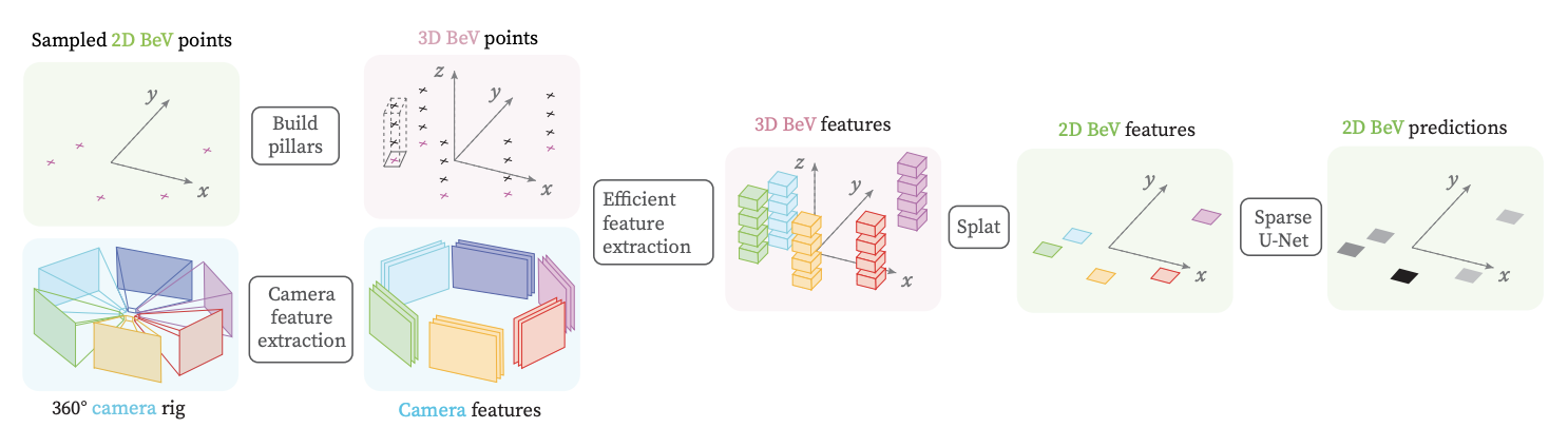
Fig 3. PointBeV Architecture
Sparse Feature Pulling and Camera Fusion
PointBeV optimizes feature extraction by projecting 3D BeV points into localized camera feature volumes and bilinearly interpolating to obtain corresponding BeV features. Unlike prior methods that redundantly project points across all cameras , PointBEV focuses only on visible points within each camera’s field of view. This approach ensures computational efficiency by performing feature pulling exclusively within relevant feature volumes, reducing unnecessary calculations while maintaining precise feature localization.

Fig 4. Sparse Feature Pulling and Camera Fusion
Coarse and Fine Training
PointBEV employs a two-stage coarse-to-fine learning strategy inspired by NeRF to selectively sample and process points in the BEV grid. The coarse stage pass uniformly samples N_coarse number of points across the grid. The fine stage focuses on regions of interest identified by the coarse stage, selecting N_anchor anchor points with the highest logits and their neighbors, a process they call densification. This hierarchical strategy balances exploration and refinement, stabilizes training, and optimizes memory usage by focusing computational resources on important areas. Additionally, this approach allows for customization, as tuning $N_{coarse}$ and $N_{anchor}$ allows users to adjust memory usage and tailor the balance between exploration and refinement.

Fig 5. Visualization of Coarse and Fine Pass
Submanifold Temporal Attention
PointBEV uses a submanifold attention mechanism to efficiently aggregate temporal information. Features from the current frame are projected into past frames using 3D-to-2D projections. A temporal threshold is applied to retain only the most relevant points based on their logits, reducing computational costs while maintaining performance.
Attention is computed locally for each query point, considering only neighboring keys and values from past timesteps, creating a sparse and computationally efficient representation.

Fig 6. Visualization of Submanifold Attention module
Results
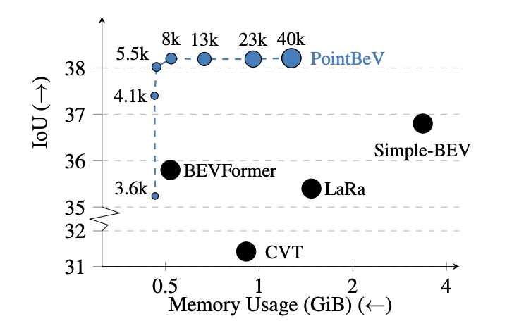
Fig 7. BeV Vehicle IoU vs memory usage on nuScenes validation set
The results are undeniable. PointBeV is able to perform better than other BeV models(as of May 2024) using less memory.

Table 1. BeV Vehicle Segmentation on nuScenes validation set

Table 2. BeV Pedestrian Segmentation on nuScenes validation set

Table 3. BeV Lane Segmentation on nuScenes validation set
PointBeV outperforms existing methods on vehicle segmentation, pedestrian segmentation, and lan segmentation across different resolutions, different backbones, and different standard visibility settings.
BeVSegFormer
Motivation
BeVSegFormer seeks to improve upon current approaches to bird’s-eye-view semantic suggestions to help bolster its critical role within both autonomous driving and robot navigation systems. One of the core components which BeVSegFormer improves upon compared to other traditional approaches is the requirement of both intrinsic and extrinsic parameters of cameras which causes inaccuracies when dealing with distant objects or occlusions. Also, many of the current approaches rely on strict frameworks and camera setups that do not generalize well when changed. BeVSegFormer seeks to build a more flexible and scalable solution which not only has increased segmentation accuracy but also can support many different camera setups.[2]
Architecture
BeVSegFormer utilizes a combination of many state of the art approaches.
- Shared ResNet backbone
- BeV transformer encoder-decoder
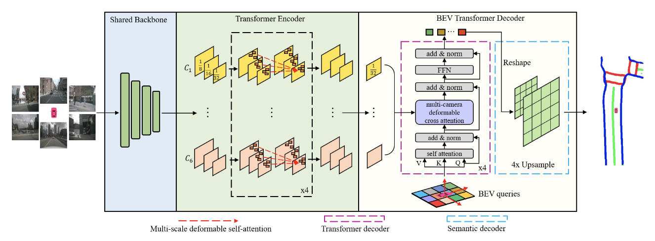
Fig 8. BeVSegFormer Architecture (Image source: https://arxiv.org/abs/2203.04050)
Backbone: For one input image the ResNet backbone outputs a multi-scale feature map and for multiple camera inputs, the same backbone is shared and outputs corresponding feature maps. Transformer Encoder-Decoder: The encoder utilizes multi-scale deformable self-attention that focuses on a set of sampling points near a reference point using the formula given below.
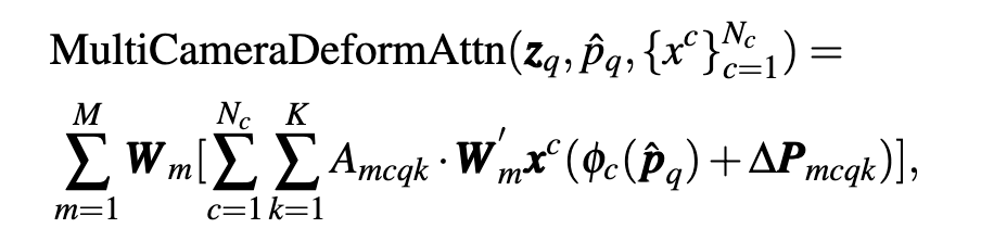
Fig 9. Formula for Multi-Camera Deformable Self-Attention (Image source: https://arxiv.org/abs/2203.04050)
Then, once encoded, the decoder computes cross-attention between the BEV queries and multi-camera feature maps. This approach adapts the DETR deformable attention module to a multicamera cross-attention module.
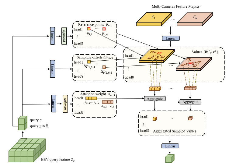
Fig 10. BEV Transformer Decoder. (Image source: https://arxiv.org/abs/2203.04050)
For each BEV query, a linear projection layer is used to predict the offset between sampling points and their corresponding reference points while sigmoid normalizing these coordinates. Then camera features from the sampled positions are collecting using the attention weights get a new query.
The BeV semantic decoder reshapes the BeV queries into a 2D spatial features which are then fed into the two-stage BeV upsample module.
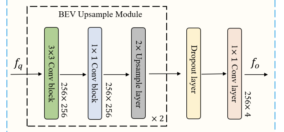
Fig 11. BeV Semantic Decoder Structure. (Image source: https://arxiv.org/abs/2203.04050)
Results
Overall, BeVSegFormer produced promising results when compared to other when compared to other state of the art approaches that also do not use temporal information.
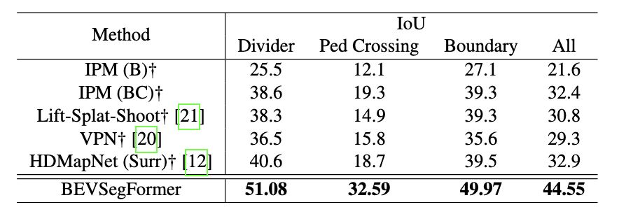
Table 4. Table with BEVSegFormer Results. (Image source: https://arxiv.org/abs/2203.04050)
As seen above, BeVSegFormer actually outperformed the other existing methods by over ten percent in detecting a road divider, pedestrian crossing, road boundaries, and the overall IoU.
In training the BeVSegFormer, ablation was used to analyze which core components worked the best which shows how certain parts of the model boosted performance for certain tasks.
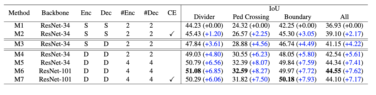
Table 5. Table with different ablation results. (Image source: https://arxiv.org/abs/2203.04050)
Below we can see some of the segmentation output of the model from both only the front camera input and the use of multiple camera inputs surrounding the vehicle.
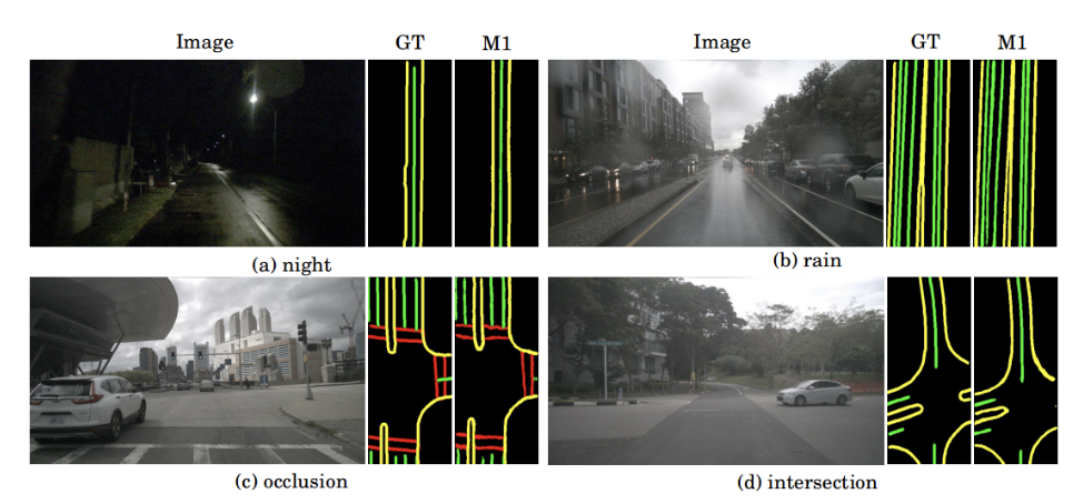
Fig 12. Single Front Camera Model Segmentation Output. (Image source: https://arxiv.org/abs/2203.04050)
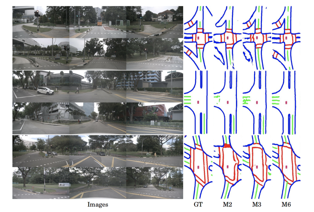
Fig 13. Multiple Camera Model Segmentation Output (Image source: https://arxiv.org/abs/2203.04050)
Conclusion
In this paper, we analyzed three different approaches to Bird’s Eye View segmentation. Lift-Splat-Shoot was a simple and efficient method to generate monocular images and has a wide variety of applications. PointBEV harnessed the power of point clouds in conjunction with BEV representations to help improve accuracy in dense and dynamic environments. BEVSegFormer used the transformer architecture to improve the scalability and accuracy of BEV segmentation with a more robust approach. All of the methods explored help advance the BEV segmentation, with the ultimate application of improving autonomous perception capabilities.
References
[1] J. Philion and S. Fidler, ‘Lift, Splat, Shoot: Encoding Images From Arbitrary Camera Rigs by Implicitly Unprojecting to 3D’, in Proceedings of the European Conference on Computer Vision, 2020.
[2] Peng, L., Chen, Z., Fu, Z., Liang, P., & Cheng, E. “BEVSegFormer: Bird’s Eye View Semantic Segmentation from Arbitrary Camera Rigs”. arXiv [cs.CV] 2022. https://arxiv.org/abs/2203.04050 References
[3] Loick Chambon, Eloi Zablocki, Mickael Chen, Florent Bartoccioni, Patrick Perez, & Matthieu Cord. (2024). PointBeV: A Sparse Approach to BeV Predictions.