Camera Pose Estimation
Camera pose estimation is a fundamental Computer Vision task that aims to determine the position and orientation of a camera relative to a scene using image or video data. Our project evaluates three camera pose estimation methods, COLMAP, VGGSfM, and depth-based pose estimation with ICP.
Introduction
Camera pose estimation has become a fundamental task in Computer Vision that aims to determine the position (translation) and orientation (rotation) of a camera relative to a scene using image or extracted video data. Accurately estimating the absolute pose of a camera has widespread applications in 3D reconstruction, world models, and augmented reality.
Camera Pose Estimation
For camera pose estimation, there are 3D-2D correspondences between a 3D point in the world (scene geometry) and the 2D pixel location where that point appears in the image or video frame.
Camera pose estimation predicts the pose of a camera with these two components:
- A translation vector: which describes where the camera is in the world coordinate system
- A rotation: which describes the camera’s orientation relative to the world
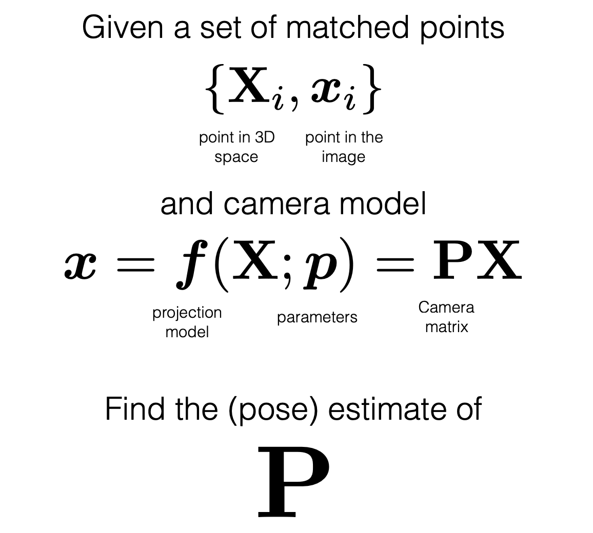
Fig 1. Overview of camera pose estimation. [8].
Camera Pose Estimation Methods
Here is an overview of the three camera pose estimation methods that we are evaluating: COLMAP, VGGSfM, and depth-based estimation with ICP.
COLMAP
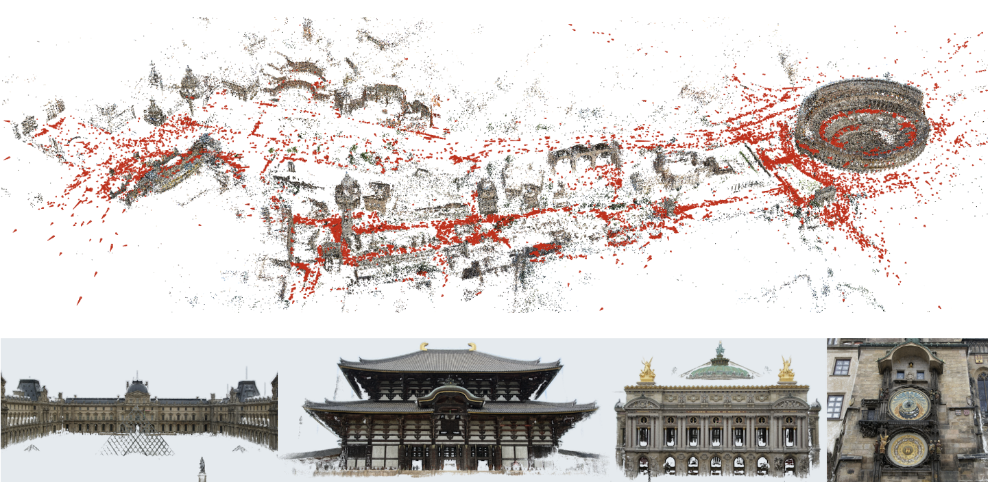
Fig 1. Example: COLMAP used for 3D scene reconstruction [2].
COLMAP is an end-to-end 3D reconstruction pipeline that estimates both scene geometry and camera poses from images. It uses Structure-from-Motion (SfM) to recover a sparse representation of the scene and camera poses of the input images. This is then fed into Multi-View Stereo (MVS) which recovers a dense representation of the scene.
The process of SfM consists of these key stages after taking in images as input:
- Performing feature detection and extraction
- Feature matching and geometric verification
- Structure and motion reconstruction
For the feature matching and geometric verification, we employ sequential matching, which is best for images that were acquired in sequential order, such as video data. Since frames have visual overlap, it is not required to use exhaustive matching. In this process, consecutive images and matched against each other.
After SfM, Multi-View Stereo (MVS) then takes that output to compute depth and/or normal information of every pixel in the image, and then it uses the depth and normal maps to create a dense point cloud of the scene. This sparse reconstruction process loads the extracted data from the database and incrementally extends the reconstruction from an initial image pair by registering new image and triangulating new points.
(a) COLMAP sparse reconstruction on freiburg1_plant
(b) Alternate view of camera trajectory and sparse points
Fig. 2. COLMAP sparse 3D points and estimated camera poses (red frustums) on the freiburg1_plant sequence
VGGSfM (Visual Geometry Grounded Deep Structure From Motion)
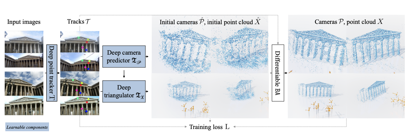
Fig 3. Overview of VGGSfM pipeline. [9].
VGGSfM is a fully differentiable, learning-based SfM (Structure-from-Motion) pipeline that jointly estimates camera poses and 3D scene reconstruction. Unlike classical SfM frameworks, which uses non-differentiable components and incremental reconstruction, VGGSfM is fully differentiable, and therefore can be trained end-to-end.
The pipeline works by:
- Extracting 2D tracks from input images
- Reconstructing cameras using image and track features
- Initializing a point cloud based on those tracks and camera parameters
- Applies a bundle adjustment layer for reconstruction refinement
Depth-based Estimation with ICP (Iterative Closest Point)
Unlike COLMAP and VGGSfM, this method does not directly operate on images/video data to estimate absolute camera positions. Instead, it uses a geometric approach that aligns two 3D points clouds and estimates the transformation (rotation and translation) between them. This transformation represents the relative camera motion between frames, which can be accumulated to form a camera trajectory.
Given the depth images from our dataset, each depth image can be projected back into a 3D point cloud using the known camera intrinsics. Iterative Closest Point (ICP) is then applied to each pair of consecutive point clouds by estimating the transformation that minimizes the spatial discrepances/sum of square errors.
This estimated transformation represents the relative camera motion between frames, and accumulating these relative motions forms the camera trajectory. This process is related to RGB-Dodometry, which produces a sequence of relative poses instead of globally optimized absolute reconstruction.

Fig 4. Overview of how ICP works. [4].
Fig 5. Overview of how ICP works. [5].
Here is our code for going from the depth images to the point cloud:
def depth_to_pointcloud(depth_path, intrinsics):
    depth = cv2.imread(depth_path, cv2.IMREAD_ANYDEPTH)
    h, w = depth.shape
    fx, fy, cx, cy = intrinsics

    u, v = np.meshgrid(np.arange(w), np.arange(h))
    z = depth.astype(float) / 5000.0
    x = (u - cx) * z / fx
    y = (v - cy) * z / fy

    valid = z > 0
    points = np.stack([x[valid], y[valid], z[valid]], axis=1)

    pcd = o3d.geometry.PointCloud()
    pcd.points = o3d.utility.Vector3dVector(points)
    return pcd.voxel_down_sample(0.02)
The transformation matrix from ICP encodes the relative camera motion between the consecutive frames, and accumulates them the estimated camera trajectory.
reg = o3d.pipelines.registration.registration_icp(
    source_pcd, target_pcd,
    max_correspondence_distance=0.05,
    init=np.eye(4),
    estimation_method=o3d.pipelines.registration.TransformationEstimationPointToPoint()
)

relative_transform = reg.transformation
Metrics
Now we will be going over the three key metrics that we used and what each of them are calculating.
Absolute Trajectory Error (ATE)
Absolute trajectory error (ATE) is a metric that is used to evaluate the accuracy of the estimated camera trajectory compared to the ground-truth trajectory. It measures the difference between the points of the true and estimated trajectory.
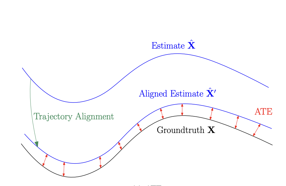
Fig 6. Example of absolute trajectory error. [10].
Relative Translation Error (RLE)
Relative translation error (RTE) is a metric that measures the accuracy of the frame-to-frame translational motion of the camera. It is a local motion accuracy metric that evaluates if the camera moved the correct distance and direction between consecutive frames, independent of global drift.
Relative Orientation Error (ROE)
Relative orientation error (ROE) is a local rotation accuracy metric, which checks if the camera rotated by the correct amount and in the correct direction between two consecutive frames. It looks at the relative rotation in the estimated trajectory compared to the ground-truth relative rotation.
Findings and Analysis
Table
Here is a table comparing the three methods using the metrics above.
| Method | ATE | RTE | ROE |
|---|---|---|---|
| VGG | 0.0214 | 0.00493 | 0.3298 |
| ICP | 0.0842 | 0.0172 | 1.5116 |
| COLMAP | 0.0477 m | 0.0073 m/frame | 0.9050 °/frame |
Analysis
Absolute Trajectory Error (ATE)
ATE captures how accurately each method reconstructs the global camera trajectory, which is critical for long web videos where drift can accumulate. VGGSfM achieves the lowest ATE, showing strong global consistency due to its end-to-end optimization of camera poses and scene structure. COLMAP performs moderately well but is more sensitive to unreliable feature matches that commonly occur in web videos. ICP performs worst, as it only estimates relative motion and lacks global optimization, causing small errors to compound over time.
Relative Translation Error (RTE)
RTE measures local frame-to-frame translation accuracy and reflects how well each method handles short-term camera motion. VGGSfM again performs best, suggesting that learned motion representations help stabilize local translation estimates under challenging visual conditions. COLMAP’s performance depends heavily on feature quality and overlap between frames, leading to higher error when these assumptions break down. ICP shows the largest error, likely due to depth noise and incomplete point cloud overlap between consecutive frames.
Relative Orientation Error (ROE)
ROE evaluates the accuracy of relative camera rotations, which is especially important in videos with abrupt or irregular motion. VGGSfM achieves the lowest rotational error, indicating stable orientation tracking across diverse scenes. COLMAP shows moderate rotational error, which can arise from weak geometric constraints in feature-based matching. ICP performs worst, as small rotational errors in each alignment step accumulate without any global correction mechanism.
Summary
Overall, the results support the project’s motivation that pose estimation accuracy varies significantly across methods when applied to web videos. VGGSfM consistently performs best due to its learning-based and globally optimized design, COLMAP provides a strong but scene-sensitive classical baseline, and ICP struggles with accumulated drift over long sequences. These differences highlight the importance of choosing pose estimation methods that are well-suited to the variability and noise present in real-world video data.
Reference
[1] Schönberger, J. (n.d.). COLMAP - Structure-from-Motion and Multi-View Stereo. https://demuc.de/colmap/
[2] Tutorial — COLMAP 3.14.0.dev0, 5b9a079a (2025-11-14) documentation. (n.d.). https://colmap.github.io/tutorial.html
[3] VGGSFM: Visual Geometry Grounded deep structure from motion. (n.d.). https://vggsfm.github.io/
[4] By Biggerj1 - Own work, CC BY-SA 4.0, https://commons.wikimedia.org/w/index.php?curid=88265436
[5] Jaykumaran, & Jaykumaran. (2025, May 10). Iterative Closest Point (ICP) for 3D Explained with Code. LearnOpenCV – Learn OpenCV, PyTorch, Keras, Tensorflow With Code, & Tutorials. https://learnopencv.com/iterative-closest-point-icp-explained/
[6] Computer Vision Group - Useful tools for the RGB-D benchmark. (n.d.). https://cvg.cit.tum.de/data/datasets/rgbd-dataset/tools
[7] System Evaluation » Filter Evaluation Metrics OpenVINS. (n.d.). https://docs.openvins.com/eval-metrics.html
[8] Kitani, K. & Carnegie Mellon University. (n.d.). Pose estimation [Lecture notes]. In 16-385 Computer Vision. https://www.cs.cmu.edu/~16385/s17/Slides/11.3_Pose_Estimation.pdf
[9] Wang, J., Karaev, N., Rupprecht, C., & Novotny, D. (2023, December 7). Visual geometry grounded deep structure from motion. arXiv.org. https://arxiv.org/abs/2312.04563
[10] Zhang, Z., Scaramuzza, D., Robotics and Perception Group, University of Zürich, & University of Zürich and ETH Zürich. (2021). A tutorial on Quantitative Trajectory Evaluation for Visual(-Inertial) odometry. Robotics and Perception Group. https://www.ifi.uzh.ch/dam/jcr:89d3db14-37b1-431d-94c3-8be9f37466d3/IROS18_Zhang.pdf